


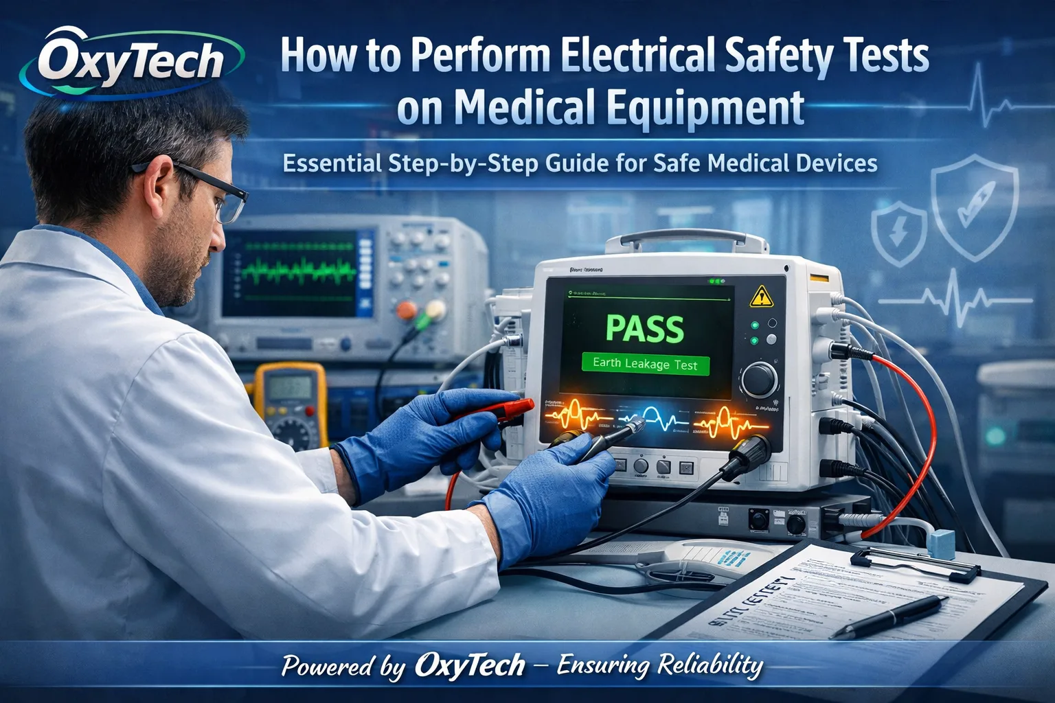
How to Perform Electrical Safety Tests on Medical Equipment
Electrical safety testing ensures Medical Devices don't harm patients or staff by preventing shocks, fires, or faults. This guide provides a step-by-step process compliant with key standards like IEC 60601-1.
Why Electrical Safety Testing Matters
Hospitals rely on equipment like defibrillators, ventilators, and infusion pumps that must operate flawlessly. Faulty wiring or insulation can lead to micro-shocks or macro-shocks, risking lives in critical care.
Testing verifies protective earth bonds, insulation strength, and leakage currents under normal and fault conditions. Regular checks—annually or after repairs—reduce liability and downtime.
Standards such as IEC 60601-1 set global benchmarks for basic safety and performance. In regions like Australia/New Zealand, AS/NZS 3551 mandates lifecycle management from commissioning to decommissioning.
Key Standards and Regulations
IEC 60601-1 is the cornerstone for medical electrical equipment (MEE), covering general safety requirements including shock protection. Collateral standards like IEC 60601-1-11 address home-use devices.
IEC 62353 guides in-service testing, focusing on field checks post-repair or before patient use. AAMI/ANSI ES60601-1 aligns with U.S. NFPA 99 for hospital settings.
Patient environments classify as "patient vicinity" or "applied parts," demanding stricter limits on patient leakage currents. Compliance proves due diligence for accreditation bodies like JCI.
Personnel Qualifications
Only trained biomedical technicians (BMETs), clinical engineers, or certified electricians should perform tests. They need familiarity with analyzers like Fluke ESA609 and risk-based decision-making.
Training covers hazard identification, standard interpretation, and pass/fail criteria. Facilities must document qualifications per ISO 14971 risk management.
In India, under the Medical Devices Rules 2017, authorized service providers ensure AE(E) certification for high-risk devices.
Required Tools and Equipment
Use a calibrated electrical safety analyzer (e.g., Rigel, Fluke, or Metron) integrating voltage checks, earth resistance, and leakage measurements. Test loads simulate faults accurately.
Accessories include test leads, reversible plugs for polarity swaps, and isolation transformers for sensitive devices. Digital multimeters serve as backups for manual checks.
Maintain a log of calibration dates—typically annual—to ensure accuracy within 2% tolerance.
Preparation Steps
Inventory and Scheduling
Create an asset register with device IDs, purchase dates, usage history, and last test. Schedule tests during low-use periods, prioritizing high-risk items like electrosurgical units.
Visual Inspection
Examine power cords for frays, burns, or pin wear; check strain relief and plugs for secure fit. Inspect enclosures for cracks, loose screws, or liquid ingress—tag out failures immediately.
Verify labels: serial numbers, ratings (Class I/II, Type B/CF/CF), and applied parts symbols. Clean devices to avoid false readings from debris.
Environment Setup
Test in a dry, controlled area away from patients. Ground the analyzer properly and use barriers to prevent accidental contact during energized tests.
Test Sequence Overview
Follow this order: visual check, protective earth continuity, insulation resistance, then leakage currents (normal condition first, faults last). Power off between tests to reset states.
Document each step with readings, conditions, and technician sign-off. Use templates from standards for consistency.
Step 1: Protective Earth Continuity
For Class I devices (earthed metal cases), measure resistance from chassis ground point to earth pin. Apply 10A current (or 25A pulse) for <0.1-0.3 ohms limit.
Analyzer probes connect to earth pin and exposed metal. Pass if under 0.2 ohms typical; fail prompts repair.
Class II (double-insulated) skips this—no earth needed.
Step 2: Insulation Resistance
Apply 500V DC between live/neutral and earth/enclosure. Expect >2-7 MΩ at sea level, derating for altitude.
Test mains to enclosure and applied parts separately. High resistance confirms no breakdown paths.
Step 3: Mains Voltage and Device Current
Verify supply voltage (e.g., 230V ±10% in India). Measure consumption with device on—compare to manual specs to detect shorts.
Step 4: Earth Leakage Current
With device off/on, measure current from live parts to earth under normal condition (NC). Limit: 5mA NC, 10mA single fault (SFC). Use meter scale for µA/mA.
Test SFC: open earth, open neutral, reverse polarity. Peak values must stay safe.
Step 5: Touch (Enclosure) Leakage Current
Probe chassis with device powered. NC limit: 100µA; SFC: 500µA. Simulates staff touch.
Step 6: Patient Leakage Current
For devices with applied parts (e.g., ECG leads), measure from part to earth. Type B/CF: stricter <10µA NC, <50µA SFC.
Test lead-to-lead and between parts. Use saline phantom for realistic contact.
Step 7: Patient Auxiliary Current
Checks current between applied parts under load. Ensures no imbalance shocks cardiac patients.
Fault Condition Testing
Simulate failures: interrupted earth, neutral, or both. Highest leakage occurs here—double limits apply but monitor peaks.
Pass/Fail Criteria Table
| Test Type | Normal Condition Limit | Single Fault Limit | Notes |
|---|---|---|---|
| Earth Continuity | <0.3 Ω | N/A | Class I only |
| Insulation Resistance | >2 MΩ | >2 MΩ | 500V DC |
| Earth Leakage | 5 mA | 10 mA | RMS/peak |
| Touch Current | 100 µA | 500 µA | Body model |
| Patient Leakage (CF) | 10 µA | 50 µA | Applied parts |
Adjust for device class/type per IEC 60601-1 Table 6.
Post-Test Actions
Pass: Affix current sticker, update inventory, return to service. Fail: Tag "OUT OF SERVICE," notify user, repair, and retest.
Archive records for 5-7 years per regulations. Trend data flags aging issues.
Common Failure Causes and Fixes
Overloaded cords cause earth bond fails—replace cables. Moisture drops insulation—dry and seal.
Capacitive leakage from filters exceeds in faults—check Y-caps. Professional repair for internals.
Advanced Testing Considerations
For networked systems, test ME systems per IEC 60601-1. High-frequency devices need EMI checks.
Portable analyzers support bedside tests; software automates reports.
Maintenance Program Best Practices
Integrate with CMMS for reminders. Risk-stratify: high-risk quarterly, low-risk biennial.
Train staff annually; audit programs for compliance.
Safety Precautions During Testing
Wear insulated gloves; use lockout/tagout. Never test on patients—simulate only.
De-energize before probes; watch for arcing.
Case Study: Ventilator Failure Prevention
A hospital found 0.5Ω earth resistance on a ventilator via routine test, averting potential ICU shock. Post-repair, leakage dropped 80%.
FAQs
How often test? Annually minimum, or post-repair/incident.
Class I vs II? I needs earth; II relies on insulation.
Cost of analyzer? $2,000-$10,000; outsource viable.
India-specific? Follow CDSCO guidelines aligning IEC.